Exploring the Power of Magnetism
Magnetism at its core
Magnetism arises from the motion of electric charges, particularly the spin and movement of electrons within atoms. At its core, magnetic behavior is governed by the interaction between magnetic fields and materials. In ferromagnetic substances like iron, the magnetic moments of atoms align in the same direction, creating strong, permanent magnets.
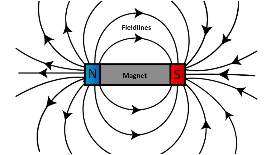
The strength and direction of a magnetic field are described by field lines, which flow from the north to the south pole. These fields can exert forces on other magnetic materials. This force is projected in the direction of the field lines, creating attraction or replusion of the magnetic objects.
Electromagnetism
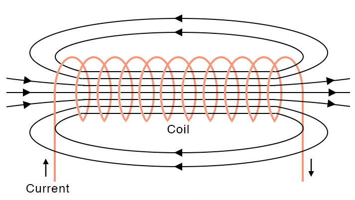
When a current flows through a wire, a magnetic field is created around it. You can find the direction of the magnetic field by using the right-hand rule: point your thumb in the direction of the current, and the magnetic field will circle around the wire in the direction your fingers curl.
This also works the other way around. Moving a magnet near a wire can induce a voltage and, in turn, create a current in the wire. The amount of current depends on the change in the magnetic field—known as flux. This principle forms the basis of Inductive Power Transfer, which will also be used later in the project.
An electromagnet is made by winding a coil. The magnetic field lines are directed through the center of the coil. The benefit of electromagnets compared to permanent magnets is that they’re more versatile. Increasing the number of turns on the coil or increasing the current strengthens the magnetic field. Flipping the direction of the current also reverses the direction of the magnetic field.
Using a permanent magnet as a core for the coil increases the strength of the electromagnet. This also works the other way around—placing a coil on a magnetic surface slightly improves induction range and efficiency
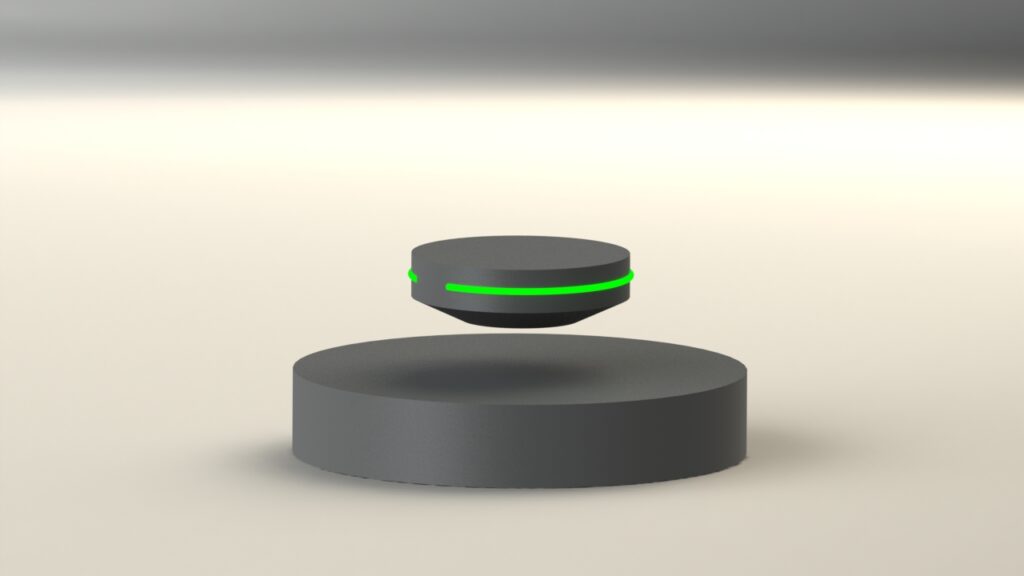
Design of the levitation platform
The levitation platform is built around a circular base that houses the magnets and electrical components responsible for balancing and suspending the floating disk in mid-air.
The floating platform itself is a sleek disk with an LED filament wrapped around its outer edge. The filament lights up automatically when the disk is levitating above the base, creating a visual cue that highlights successful stabilization.
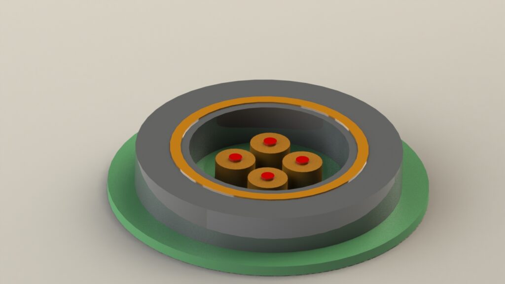
Looking inside
The base platform houses a large ferrite ring magnet, which provides the main magnetic force for levitating the floating disk. At the center of the ring, four identical electromagnets are placed. These electromagnets connect to a control circuit that activates them based on the position of the floating platform.
The control circuit includes Hall-effect sensors that measure the surrounding magnetic field. With two sensors, movement along the X and Y axes can be detected. This feedback is used to selectively activate the electromagnets, correcting the disk’s position and keeping it stable—giving the illusion of perfect stillness.
Mounted directly on the ferrite magnet is a coil used for inductive power transfer. This coil wirelessly powers the LED filament embedded in the floating disk when it hovers above the base, linking form and function with a seamless glow.
Circuit Design—Power & Stabilization
The levitation circuit is divided into two parts: a small module for powering the LED, and a larger control circuit responsible for stabilizing the floating platform.
Stabilization:
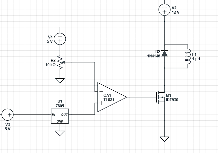
The control system begins with two Hall-effect sensors, each powered by a steady 5V supply from a 78L05 voltage regulator. The output from the sensors is sent to an operational amplifier (op-amp), which amplifies the signal once it passes a set threshold. This threshold is fine-tuned using a potentiometer connected to the op-amp’s negative input.
The amplified output from the op-amp is connected to the gate of an N-channel MOSFET. The MOSFET then acts as a switch, allowing current to flow through the electromagnet only when needed.
Because the electromagnets switch rapidly, a flyback diode is placed in parallel with each coil to protect the circuit from damaging voltage spikes caused by sudden changes in current.
This circuit is then replicated and combined for all 4 magnets.
This part of the project is currently still in development. Once the final schematic of the circuit is complete, it will be added here and made available for download to anyone interested.